Technical analysis · Graphitization overview -- Graphitization furnace and auxiliary equipment

Technical analysis · Graphitization overview -- Graphitization furnace and auxiliary equipment
Graphitization furnace is direct heating and intermittent operation resistance furnace designed according to the principle of Joule's law. EAF furnace steelmaking used standardized graphite electrodes for reference. For Acheson graphitization furnace, the product installed in the furnace and a small amount of resistance material constitute the furnace core, and the product itself is not only the heating resistance, but also the heating object. For the internal series furnace, the product loaded into the furnace is the furnace core, and the heating resistance is composed of the product itself. Products are graphitized by their own heating.
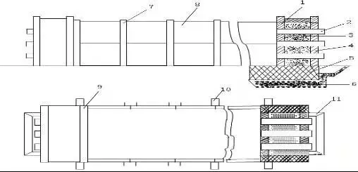
Acheson graphitization furnace generally includes furnace bottom groove, furnace head end wall, conductive electrode, furnace side wall, channel steel, etc.
Fig. 3-1 Acheson graphitization furnace structural diagram

Furnace bottom groove generally refers to the lower part of the rectangular groove between the walls at both ends of the graphitization furnace. On the concrete foundation of graphitization furnace, first build 1 ~ 3 layers of red bricks, and then build a layer of ordinary refractory bricks. The surrounding areas are also built with refractory bricks to the ash carbon block on the end wall. If the movable side wall type is adopted, a row of tiger head bricks shall be built on both sides to form the furnace bottom groove.
A conductive end wall is built at both ends of the furnace trough to form the furnace head end wall. The outer wall of the furnace head end wall is built with multi ash carbon blocks or refractory clay bricks, high alumina bricks, etc. The inner wall is built with graphite blocks. In order to strengthen the protection of the furnace head so that it will not cause large deformation and damage under the impact of thermal expansion or mechanical force, there are protective frames made of channel steel or angle steel on both sides of the furnace head and fixed with cable braces. The space between the inner and outer sides of the wall is filled with graphite powder and tamped. The moisture content of graphite powder is less than 0.5%, the particle size is between 0 and 5 mm, the ash content is less than 1.5%, and the resistivity of the powder is not more than 350×10-6 ohm·m. The purpose of loading graphite powder is:
(1) Sealing and heat preservation effect.
(2) At the same time, it also has the effect of partial equalizing current.
Many manufacturers choose to put a layer of refractory brick or waste anode on the furnace head graphite powder to cover it. The main function of the cover is to enhance the sealing effect and prevent the heat preservation material from mixing into the graphite powder of the furnace head. When the preservation material of the upper cover is mixed with graphite powder, it is easy to form hard blocks.
The conductive electrode passes through the inner and outer end walls and forms a whole with the end wall. A copper plate on the electrode is connected with it through a clamping fixture. The copper plate and the aluminum busbar are connected with multiple layers of thin copper sheet buffer. The end of the electrode leaning towards the furnace is connected with the conductive end wall inside the furnace.
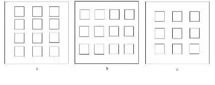
The conductive electrode can be graphitized electrode or graphite block. Conductive electrodes can be graphitized electrodes or graphite blocks. If the graphitized electrode is used as the conductive electrode, it will bring great difficulty to the construction of the graphitized furnace. Therefore, the conductive electrode is mostly used graphite block. The graphite block should have a high conductivity, and its allowable current density should be more than 11 A/cm2. Therefore, many manufacturers now use second baking graphite block as conductive electrode. Considering the non-uniformity of the conductivity of each conductive electrode due to various reasons such as the degree of connection, in order to improve the service life of conductive electrode, the number and section of graphitized conductive electrode should be selected to ensure that the current density is less than 10 A/cm2. Otherwise, the conductive electrode is easy to break, which is easy to cause the fire channeling accident of the furnace head (tail) conductive end wall in the later stage of power transmission.
Fig. 3-2 Conductive electrodes configuration on the conductive end wall of the furnace head (tail)

The cross section of commonly used graphite block is generally more than 400 × 400, the resistivity should be less than 10×10-6 ohm·m, and the compressive strength is greater than 16MPa. Contacting us for the latest news of graphitization furnace.
Table 3-1 Physical and chemical indexes measured results of graphite blocks.
Item | Index |
Ash content | 0. 32% |
True density | 2. 22g\cm2 |
Bulk density | 1. 61 〜1. 67 g\cm2 |
Porosity | 24. 77〜27. 48% |
Compressive strength | 20〜29MPa |
Specific resistance | 8〜10×10-6Ω·m |
No related results found


0 Replies